Creating accurate BIM models requires detailed and precise components. When working with existing buildings or complex objects, standard Revit families may not be enough. This is where Scan to Revit Family Creation plays an important role. It helps convert real-world objects into intelligent, parametric Revit families using scanned data.
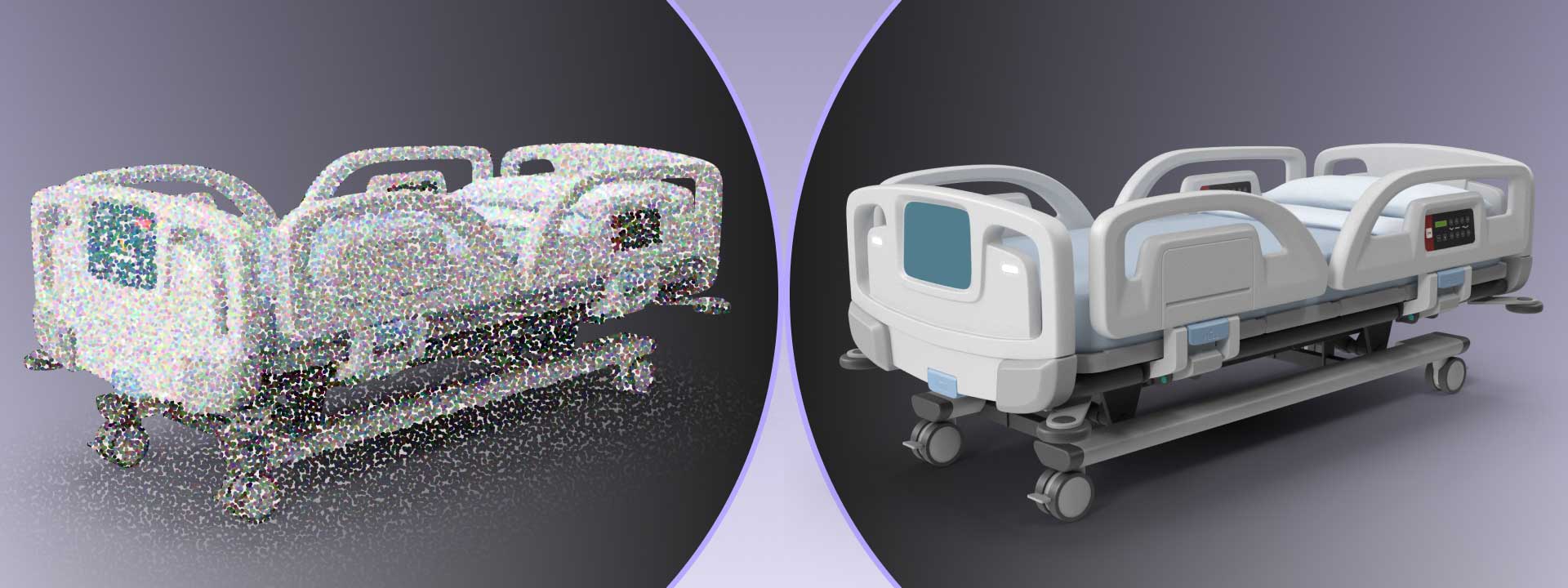
With advanced 3D laser scanning and LiDAR technology, professionals can capture highly accurate measurements of physical elements. These scans generate a point cloud, which serves as the foundation for creating Revit families. By using this data, BIM teams can replicate real-world components with precision, making the models more reliable for design, renovation, and facility management.
Scan to Revit Family Creation is widely used in architecture, construction, and MEP projects. It improves coordination, reduces errors, and ensures that digital models match existing site conditions. Whether it’s a structural element, an MEP component, or custom furniture, this approach enhances efficiency in BIM workflows.
What is Revit Family?
Revit families are pre-built components used in Building Information Modeling (BIM). They include architectural, structural, and MEP elements like doors, windows, columns, pipes, and mechanical equipment. Each family has parametric data that control its size, shape, and behavior. These parameters allow customization based on project requirements.
Types of Revit Families
Revit families are classified into three main categories:
-
System Families – These are built into the Revit environment and cannot be loaded from an external file. They include elements like walls, floors, ceilings, roofs, and ducts. System families define the core structure of a BIM model.
-
Loadable Families – These are external components created in the Revit Family Editor and can be imported into projects. Loadable families are used for elements like doors, windows, furniture, mechanical equipment, and fixtures. They allow for greater customization and can include nested families, which combine multiple elements into a single, reusable component.
-
In-Place Families – These are custom families created within a specific project. They are used when unique design elements are needed, such as custom millwork or site-specific structural components. In-place families are not reusable across different projects.
Learn more about the Different Kinds of Families
Revit Family Components
| Category | Components |
|---|---|
| Architectural | Walls, Doors, Windows, Roofs, Floors, Stairs, Railings |
| Structural | Columns, Beams, Trusses, Bracing, Foundations, Connections |
| Mechanical (HVAC) | Ducts, Fittings, Air Handling Units (AHU), Chillers, Boilers, Fans, Diffusers |
| Electrical | Lighting Fixtures, Electrical Panels, Switchboards, Cables, Conduits, Fire Alarm Systems |
| Plumbing | Pipes, Valves, Water Supply Fixtures, Drainage Systems, Pumps |
| Firefighting | Sprinkler Systems, Fire Extinguishers, Hydrants, Hose Reels, Smoke Detectors |
| Interior (Furniture & Fixtures) | Beds, Sofas, Chairs, Tables, Cabinets, Decorative Elements |
| Other Components | Signage, Landscaping Elements, Equipment, Custom Families |
Revit Families and BIM Objects
BIM objects are digital representations of real-world building components that store geometric, material, and performance data. Revit families act as BIM objects within a project, ensuring consistency in design and construction. They contain parameters such as:
- Type Parameters – Apply changes to all instances of a family type (e.g., width and height of a door type).
- Instance Parameters – Modify specific instances without affecting others (e.g., adjusting the height of a single column).
- Material Parameters – Define surface finishes, textures, and physical properties for visualization and analysis.
Revit family creation can also include parametric constraints, formulas, and visibility settings to control their behavior in different views. They support Level of Development (LOD) variations, ranging from basic geometric representations to highly detailed models with fabrication-ready information.
What exactly is Scan to Revit Family Creation?
Scan to Revit Family Creation is the process of converting laser-scanned data of physical objects or building components into parametric Revit families. This workflow uses point cloud data captured through 3D laser scanning to generate accurate BIM objects with precise geometry and metadata. The resulting Revit families can be used for design, analysis, restoration, facility management, and digital twin development in various industries, including architecture, engineering, construction, and manufacturing.
The Role of 3D Laser Scanning in Creating Accurate Revit Families
3D laser scanning plays a crucial role in generating accurate Revit families from real-world objects. It captures detailed geometric and spatial data using high-precision laser scanners or LiDAR technology. This data is converted into a point cloud, which serves as a digital representation of physical objects. By using point clouds, BIM professionals can create precise parametric Revit families that match existing conditions with minimal errors.
How 3D Laser Scanning Helps in Revit Family Creation?
-
Capturing Detailed Geometry – Laser scanning records the exact dimensions and shape of objects, ensuring accurate modeling in Revit. This is essential for complex components like industrial equipment, structural elements, and MEP systems.
-
Ensuring High Accuracy – Scanned data provides millimeter-level precision, reducing manual measurement errors. This accuracy is critical when creating custom Revit families for renovation, retrofitting, or heritage preservation projects.
-
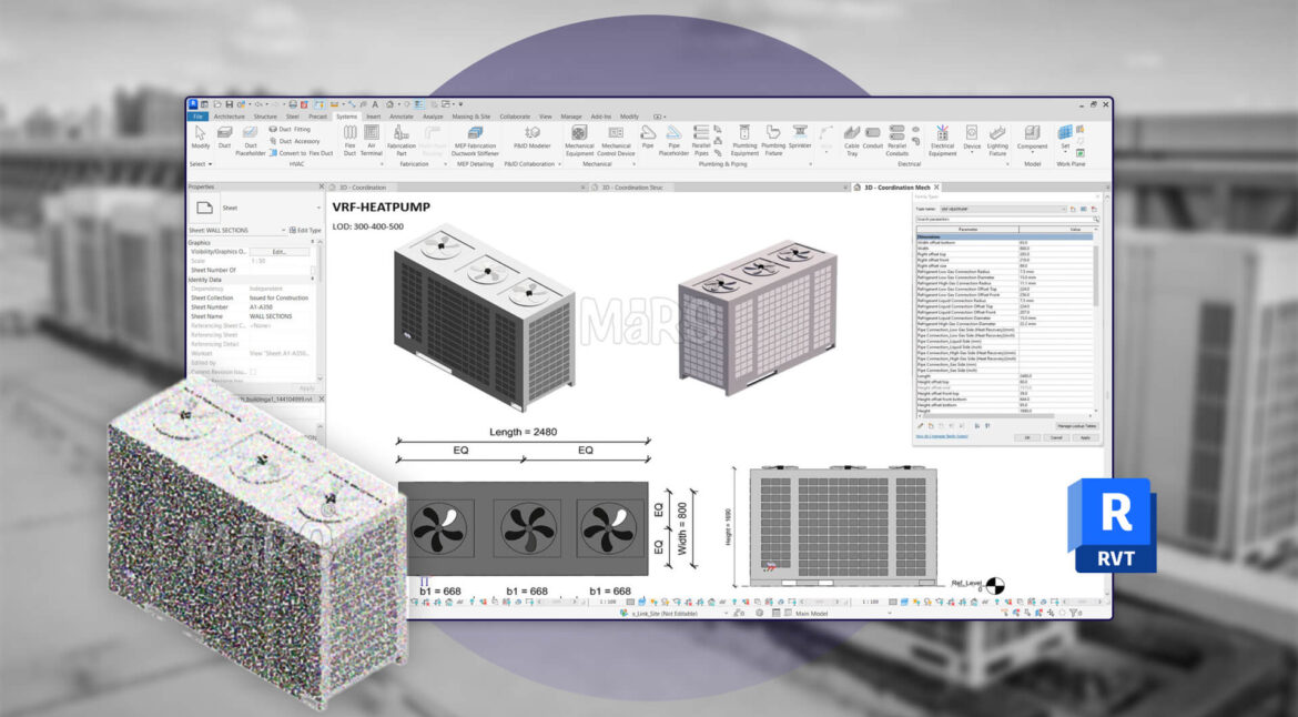
Converting Point Cloud to Revit Families – The point cloud data is imported into software like Autodesk ReCap, or directly into Revit. BIM experts use this data to create parametric families by tracing and modeling components with appropriate levels of detail (LOD 300, 400, or 500).
-
Reducing Time and Rework – Traditional modeling methods rely on manual measurements, which can lead to inconsistencies. Laser scanning streamlines the process by providing precise as-built conditions, minimizing rework, and improving efficiency.
-
Supporting Complex and Custom Elements – Some objects, such as historical architectural details, irregular structural elements, or MEP equipment, are difficult to model manually. Laser scanning captures their intricate details, ensuring that the Revit families accurately reflect real-world conditions.
Process to Create Revit Families from Scanned Data
Creating Revit families from scanned data follows a structured process. It involves capturing, processing, and converting point cloud data into accurate BIM components. The process may include point cloud to mesh conversion, which helps in modeling complex objects before integrating them into Revit.
1. Data Capture Using 3D Laser Scanning
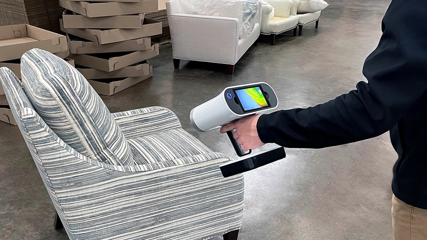
A 3D laser scanner or LiDAR device captures high-precision data of real-world objects. The scanner generates a point cloud, which consists of millions of data points representing the object’s geometry. This step ensures detailed and accurate measurements.
Pro Tip
Place small reference objects of known dimensions in your scan area. This provides a quick visual verification of scale accuracy during processing.
2. Point Cloud Processing
Raw scan data requires processing before it becomes useful. This step includes:
Registration and Alignment:
- Target-Based Registration: This uses physical targets placed in the scan area. It provides high accuracy.
- Cloud-to-Cloud Registration: This matches overlapping areas between scans. It works well with sufficient overlap (30-40%).
- Survey Control Integration: This link scans to established survey points. It ensures proper positioning in real-world coordinates.
Noise Reduction and Cleaning:
- Outlier Removal: This eliminates points far from the main cloud. These often result from reflections or scanner errors.
- Decimation: This reduces point density in over-sampled areas. It improves processing efficiency.
- Segmentation: This divides the point cloud into logical sections. It makes further processing more manageable.
Segmentation Techniques:
- Manual Segmentation: This involves user selection of specific areas. It works best for complex or unique objects.
- Automatic Segmentation: This uses algorithms to identify planes, cylinders, and other geometric primitives.
- Region Growing Methods: These start from seed points. They expand based on similar properties like normal direction or color.
3. Geometry Extraction
This step transforms point cloud data into solid geometry. The approaches include:
Pattern Recognition Methods:
- Plane Detection: This finds flat surfaces like walls, floors, and ceilings. It forms the basis of architectural elements.
- Cylinder Detection: This identifies pipes, columns, and cylindrical objects. It is essential for MEP components.
- Edge Detection: This locates boundaries between different elements. It helps define object limits.
Manual vs. Automated Approaches:
- Manual Tracing: This involves drawing directly over point clouds. It offers control but requires more time.
- Semi-Automated Tools: These suggest geometry based on point clusters. They require user verification.
- Fully Automated Systems: These use machine learning to recognize common elements. They work best with standard components.
Example
A manufacturing facility needed to document 1,250 mechanical components. The team used automated cylinder detection for piping. This reduced modeling time from an estimated 320 hours to 85 hours. The final model achieved 98.7% dimensional accuracy compared to control measurements.
Level of Detail Considerations:
- LOD 200: Basic geometry with approximate dimensions.
- LOD 300: Precise geometry with accurate dimensions.
- LOD 400: Detailed geometry including connections and fabrication details.
- LOD 500: As-built representation with maintenance information.
Pro Tip
Before starting any scan project, define your required Level of Detail/Development (LOD). This will determine the scanning resolution you need. Higher LOD requires denser point clouds.
3. Importing the Point Cloud into Revit
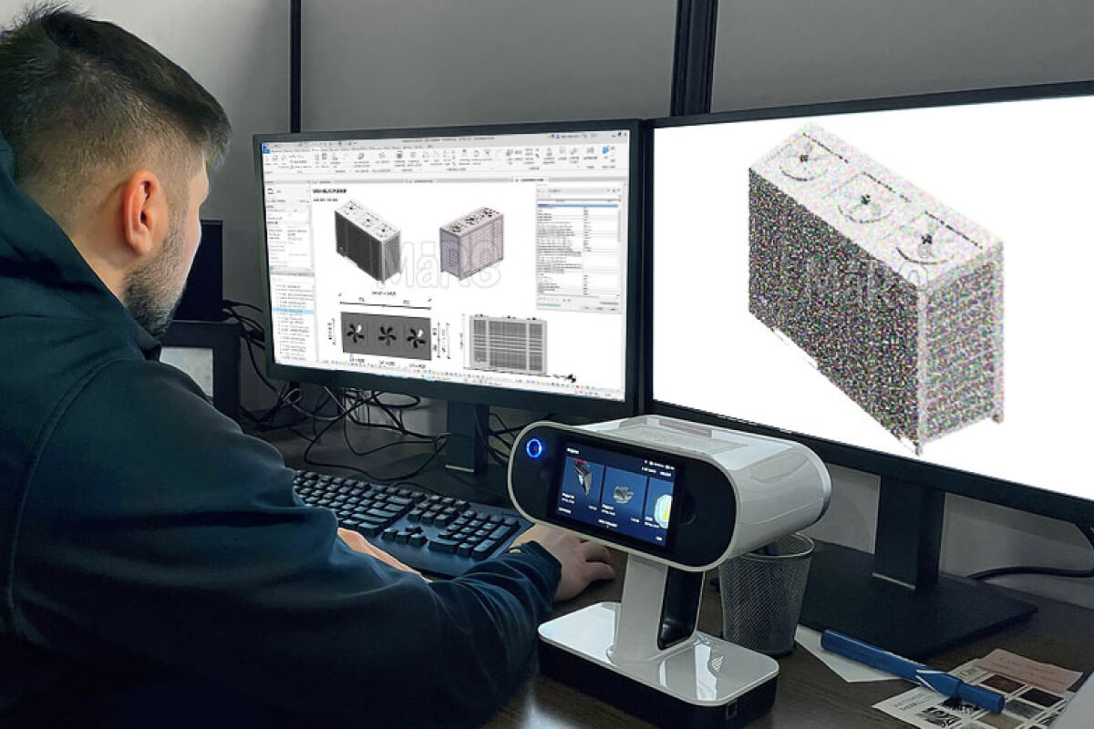
The point cloud or mesh is imported into Revit for modeling. Users adjust its scale and position to align it with the project settings. Revit’s visibility and sectioning tools help focus on specific areas for precise modeling.
4. Tracing Geometry and Creating 3D Models
Using point cloud snap tools, BIM professionals trace key features of the scanned object. Revit’s extrude, sweep, blend, and revolve functions help create accurate solid geometry. If using a mesh, it may be converted into a Revit family by recreating its geometry with parametric features.
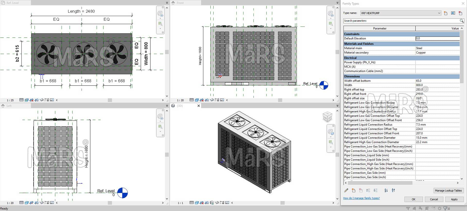
5. Defining Parameters and Constraints
The created model is transformed into a Revit family by adding parametric constraints. Users define dimensions, materials, categories, and visibility settings to ensure flexibility in BIM projects.
6. Testing and Validation
The Revit family undergoes accuracy checks to verify its dimensions, alignment, and parametric functionality. Any inconsistencies are corrected before finalizing the family.
7. Exporting and Using the Revit Family
The final Revit family (.rfa file) is saved and added to the BIM library. It can now be used in construction documents, coordination models, and facility management workflows.
Tools to Create Revit Families from Scanned Data
Creating Revit families from scanned data requires specialized tools. These tools process point cloud data and help convert it into accurate BIM components. They support different workflows, from direct modeling to parametric family creation.
1. Autodesk ReCap
Autodesk ReCap is used to process raw point cloud data from laser scanners. It helps clean, align, and convert scans into a usable format for Revit. The processed point cloud is then imported into Revit for modeling.
2. Revit Point Cloud Tools
Revit has built-in tools to work with point cloud data. Users can insert point clouds, adjust visibility, and trace geometry to create parametric families. Snapping to point clouds helps ensure precise modeling.
3. CloudWorx for Revit
CloudWorx, developed by Leica Geosystems, allows direct integration of large point cloud datasets into Revit. It provides tools for clipping, sectioning, and accurate tracing. This is useful for modeling complex elements with high precision.
4. Scan to BIM Plugins
Several Scan to BIM plugins automate the conversion of point cloud data into Revit families. These tools use advanced AI and pattern recognition to detect elements like pipes, walls, and structural components. Examples include:
- Scan to BIM by IMAGINiT – Automates the extraction of architectural and MEP elements.
- PointSense for Revit – Provides enhanced workflows for tracing and modeling scanned objects.
- Undet for Revit – Helps manage large point clouds and improves workflow efficiency.
5. Mesh Processing Software
Some scanned data needs mesh conversion before modeling in Revit. Tools like MeshLab and Autodesk MeshMixer help process complex geometries. The refined data is then imported into Revit for further modeling.
6. Dynamo for Automating Family Creation
Dynamo is a visual programming tool for automating tasks in Revit. It helps convert point cloud data into adaptive components and parametric Revit families. Dynamo scripts can generate custom objects based on scanned measurements.
How does Scan to Revit Family support various industries?
Heritage Architectural Design
Heritage buildings require accurate documentation for preservation and restoration. Traditional methods often fail to capture the detailed features of historic structures. Scan to Revit Family helps convert real-world heritage elements into digital BIM objects with high accuracy. Laser scanning captures complex architectural details such as moldings, arches, and columns. These scanned elements are then modeled into Revit families, ensuring that historical accuracy is maintained in digital form.
Architects and engineers use these BIM models to plan restoration and conservation efforts. The parametric nature of Revit families allows adjustments while keeping the original design intent intact. Structural engineers analyze scanned data to assess the stability of heritage structures. The digital model helps identify areas that need reinforcement or repairs. Scan to Revit Family also supports adaptive reuse projects. Designers can modify historical elements while keeping their original aesthetics. This ensures that new construction integrates seamlessly with heritage architecture.
MEP Engineering
MEP engineers need precise data for designing and upgrading building systems. Scan to Revit Family helps convert existing mechanical, electrical, and plumbing components into BIM objects. This ensures that engineers work with accurate as-built conditions. Scanned MEP systems help in space planning, clash detection, and coordination with other building elements. Engineers can replace outdated systems without disrupting existing structures.
Prefabrication also benefits from Scan to Revit Family. When MEP components are digitized, they can be fabricated off-site with high precision. This reduces errors during installation and speeds up construction. The BIM model allows engineers to analyze system performance and make data-driven decisions. Revit families ensure consistency in MEP designs across multiple projects.
Facility Management
Facility managers use digital models for maintenance, asset tracking, and space management. Traditional facility management relies on 2D drawings and physical inspections. Scan to Revit Family provides an accurate BIM model that represents real-world conditions. Facility managers can track building components, such as HVAC systems, electrical panels, and plumbing networks.
With Revit families, facility teams can plan repairs and replacements efficiently. They can simulate maintenance schedules and predict system failures before they happen. The digital model integrates with facility management software, enabling real-time data updates. This improves decision-making and reduces operational costs. Scan to Revit Family ensures that facility teams have reliable data for managing building systems effectively.
Digital Twin
A digital twin is a virtual representation of a building and its systems. Scan to Revit Family plays a key role in creating digital twins for architectural, structural, and MEP elements. Laser scanning captures the exact dimensions of building components, converting them into Revit families with parametric properties. These BIM models act as a real-time reference for monitoring system performance.
Digital twins help in predictive maintenance and energy analysis. Facility teams use these models to track system performance and detect inefficiencies. MEP engineers analyze scanned data to optimize heating, ventilation, and electrical systems. The digital twin improves asset management by providing a centralized platform for real-time data. Scan to Revit Family helps create a reliable and data-rich digital twin for smarter building management.
Manufacturing
Manufacturers use Scan to Revit Family to create accurate BIM models of their products. Scanning real-world objects helps generate parametric Revit families that match product specifications. This ensures that engineers and architects have access to precise digital models for integration into their designs. Manufacturers can offer Revit-compatible product catalogs to their customers, making it easier to specify products in BIM projects.
Customization is another key advantage. Manufacturers can provide multiple configurations of their products within a single Revit family. This allows architects to select different sizes, materials, or finishes within the BIM environment. Scan to Revit Family streamlines product visualization, design coordination, and prefabrication workflows.
Design Inspiration
Architects and designers use real-world objects as references for new designs. Scan to Revit Family enables them to capture and modify existing structures for conceptual development. Designers can scan sculptures, facades, and furniture, converting them into digital models for further exploration. This process helps in preserving design intent while allowing for modifications.
Conceptual massing also benefits from Scan to Revit Family. Architects can analyze the geometry and proportions of scanned elements, incorporating them into new designs. This workflow helps blend historical and modern architecture seamlessly. Digital models from scanned data serve as a foundation for customized and innovative design solutions.
Furniture Products Marketing
Furniture manufacturers and retailers benefit from BIM-based marketing strategies. Scan to Revit Family helps create detailed 3D models of furniture products for use in BIM projects. These models allow architects and designers to integrate furniture into their designs effortlessly.
With Revit families, manufacturers can showcase their products in a BIM-ready format. Designers can visualize different furniture layouts within Revit projects. Parametric models enable customization, allowing users to adjust sizes, colors, and materials within the BIM environment. This enhances product visibility and encourages architects to specify these products in their projects.
Applications and Use Cases
- It helps architects and designers integrate real-world scanned objects into their design process, enhancing visualization and creative exploration.
- Architectural heritage documentation includes historic building documentation, preservation planning, and cultural heritage archives. Preserves architectural details of historical structures by converting scanned elements into accurate Revit families for restoration and adaptive reuse.
- Converts existing mechanical, electrical, and plumbing components into BIM objects, aiding in accurate system analysis, retrofitting, and prefabrication. MEP system modeling covers mechanical room documentation, ductwork routing, and equipment replacement planning.
- Creates a digital database of building components, enabling efficient maintenance planning, space management, and lifecycle tracking for Facility Management and Asset Tracking.
- Supports real-time monitoring and predictive maintenance by providing accurate BIM representations of architectural, structural, and MEP elements.
- Custom furniture and fixture replication involves custom millwork documentation, historical fixture replication, and custom component libraries.
- Complex structural element documentation includes connection detail modeling, post-tensioned concrete documentation, and structural deformation analysis.
- Converts physical products into Revit families, allowing manufacturers to provide BIM-ready product catalogs for architects and engineers.
- Provides accurate as-built conditions for comparing new designs with existing structures.
- Enables product manufacturers to create parametric Revit families for furniture, lighting, and building components. This BIM-Based Marketing and Product Showcasing makes their products BIM-ready for architectural projects
Final Words
Scan to Revit Family Creation transforms real-world objects into accurate BIM components, improving design accuracy and project coordination. It plays a crucial role in heritage conservation, MEP modeling, facility management, and manufacturing. With advanced scanning technologies and Revit tools, professionals can create precise parametric families that enhance project efficiency. As the industry moves toward data-driven workflows, this process will continue to support better planning, design, and maintenance across various sectors.
Common Questions About Scan to Revit Family
What is the difference between Scan to BIM and Scan to Revit Family?
Scan to BIM Services creates the entire building model from scan data. It focuses on overall building geometry. Scan to Revit Family specifically creates parametric components. These components can be placed in any project. Scan to Revit Family requires a more detailed parameter setup.
How do I handle reflective or transparent surfaces?
Reflective and transparent surfaces present challenges for laser scanning. Use these techniques:
- Adjust scanner settings for high-reflectivity mode
- Scan from multiple angles
- Apply temporary matte spray to highly reflective surfaces
- Use photogrammetry as a supplement for problematic areas
- Model glass and mirrors based on their frames
What LOD (Level of Development) can I achieve?
Scan to Revit can achieve LOD 300-350 with standard workflows. With additional effort and verification, LOD 400 is possible for specific elements. Full LOD 500 requires supplementing scan data with manufacturer information and maintenance records.
Learn more about the Level of Detail/Development (LOD) here.
Can AI automatically create Revit families from scans?
Current AI solutions offer partial automation. They can identify common elements like doors, windows, and standard MEP components. Complex or custom elements still require manual modeling. The technology improves rapidly. Full automation for standard elements is expected within 3-5 years.
How do I validate the accuracy of my Revit families?
Implement these validation methods:
- Compare key dimensions against control measurements
- Use deviation analysis between the model and point cloud
- Create color-coded deviation maps
- Verify parameter behavior through family testing
- Conduct peer reviews of complex families
- Test families in different project contexts
How do I integrate Scan to Revit with facility management systems?
Follow these steps:
- Use consistent naming conventions aligned with FM systems
- Implement COBie data standards
- Use shared parameters that match FM database fields
- Create appropriate view templates for maintenance use
- Include equipment data from manufacturer specifications
- Establish clear handover procedures
- Provide training to FM staff on model usage
If you have any questions, feel free to drop them in the comment section below!