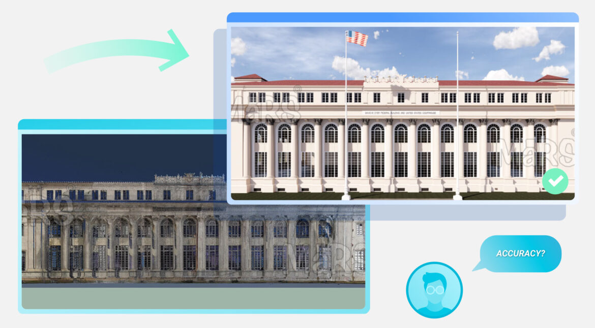
Accuracy is one of the most important parts of the Scan to BIM Services. The goal is to capture real-world spaces and create a model that reflects them exactly. Both the point cloud and the BIM model must stay close to the actual physical site. Even a small error can cause big problems later in the project.
Laser scanners can capture millions of data points within minutes, but the quality of this data depends on the tools, site conditions, and workflows. Once collected, the point cloud must be carefully processed and modeled. Each step in scanning, registration, modeling, and quality check must meet the accuracy goals defined at the start. Consistency in accuracy ensures that the model can support design, coordination, prefabrication, and facility operations without costly rework.
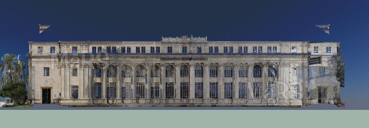
Point Cloud Accuracy
A point cloud is a group of points captured by a laser scanner. These points form a digital version of the space. Point cloud accuracy can vary depending on the technology used, the way the scan is set up, and how the data is processed. Advanced tools like LiDAR can reach sub-centimeter or even sub-millimeter accuracy, according to Autodesk. Other scanning methods may offer lower precision. Sensor limitations, surface reflectivity, and movement during scanning can also affect the results. To improve accuracy, teams often use multiple scans from different angles. A careful registration and quality control process helps reduce errors and ensures the final point cloud reflects the physical site as closely as possible.
The accuracy of a point cloud depends on a few key factors:
1. Type of Scanner
- Terrestrial scanners like Leica or FARO are very accurate. They usually have a range of ±1 mm to ±5 mm.
- Handheld or mobile scanners are faster but less accurate. Their accuracy ranges from ±5 mm to ±20 mm.
2. Scan Resolution and Range
- High resolution scans capture more detail. This gives a better shape of walls, floors, and objects.
- Accuracy drops at long distances. Most scanners work best within 30 to 60 meters.
Tip: More scanning positions reduce blind spots and improve coverage.
3. Scan Registration
Each scan must align with the others. This step is called registration. Software like Leica Cyclone or FARO Scene handles this. A good registration has an error of less than ±2 mm.
Note: If multiple scans are not aligned correctly, gaps or shifts can appear in the final point cloud.
4. Environment
- Shiny, glass, or dark surfaces can confuse the scanner.
- People or movement during scanning can add extra noise.
BIM Model Accuracy
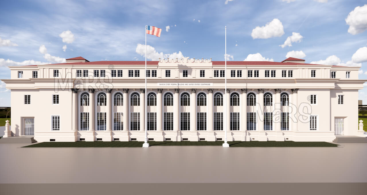
Once you have the point cloud, you can create the BIM model. This model uses the scan data as a guide. BIM accuracy depends on how closely the model matches the scan.
1. Use of Clean Scans
- Only use registered and filtered point clouds.
- Remove noise and unwanted objects before modeling.
- Take horizontal or vertical slices for clear geometry tracing.
2. Modeling Level of Detail (LOD)
- LOD 100–200 – Basic shapes and approximate sizes. Used for early planning.
- LOD 300 – Accurate geometry and spatial relationships. Used for design and coordination.
- LOD 400 – Includes fabrication and installation details. Requires very high accuracy.
- LOD 500 – Represents the actual as-built condition, with full information for operations.
Note: Higher LOD takes more time but gives better accuracy.
3. Defined Tolerance
- Tolerance means the allowed difference between the real site and the model.
- Common tolerances:
- ±10 mm for architectural models.
- ±5 mm for MEP or fabrication work.
- Set the tolerance at the start of the project.
4. Manual Modeling Errors
- Mistakes can happen during manual tracing.
- Some modelers guess shapes when the point cloud is unclear.
- Always check the model with section views and QA tools.
Other modeling factors that affect accuracy:
- Modeler’s experience – Skilled users can interpret complex or unclear point clouds more effectively.
- Scan-to-model tolerance – Some projects set a tolerance range (e.g., ±10 mm) to ensure model elements stay within limits.
- Object classification – Proper naming, tagging, and parameter settings are important for reliable use later.
- In most commercial projects, a well-managed Scan to BIM workflow can deliver a model with ±10 mm or better accuracy when using high-quality scanners and experienced teams. This is usually acceptable for design, renovation, clash detection, and documentation.
- Projects requiring tighter tolerances, such as industrial retrofits or prefabrication, need LOD 400 or higher, and may involve multiple scans, higher-resolution settings, and stricter QA processes.
- A quality Scan to BIM model is only as accurate as the data and methods behind it. For critical use cases, clear accuracy requirements should be defined at the start. This includes scanning specifications, modeling standards, and quality checks throughout the process.
Read How is a 3D Model created in the Scan to BIM Process?
Accuracy Expectations
| Workflow Step | Expected Accuracy |
| High-End Laser Scanning | ±1 mm to ±3 mm |
| Medium-Quality Scanning | ±5 mm to ±10 mm |
| Registered Point Cloud | ±2 mm to ±5 mm overall |
| BIM Model (LOD 300) | ±10 mm to ±20 mm |
| BIM Model (LOD 500) | ±5 mm or better |
Why Accuracy Matters?
When the model is accurate, the whole project runs better. Teams communicate clearly, reduce delays, and make decisions with confidence. That’s why accuracy is not just a technical detail — it’s a key factor in project success.
Accurate models reduce mistakes during construction.
When the BIM model reflects real-world conditions, construction teams can follow it with confidence. Accurate models remove the guesswork. Workers can install pipes, ducts, and walls without unexpected changes on-site. This reduces delays, saves labor, and avoids costly rework. It also improves safety because fewer adjustments need to be made during active construction.
Good accuracy helps detect clashes early.
Clash detection is one of the key uses of BIM. When Scan to BIM models are accurate, clash detection becomes more reliable. MEP, structural, and architectural elements can be checked against each other in the model. If there’s a conflict, teams can solve it in the design phase. This prevents delays and change orders later. Accurate geometry also reduces false clashes caused by modeling errors.
Fabricators can use the model to build custom parts.
Prefabrication depends on precise measurements. Fabricators rely on BIM data to cut materials and build components off-site. If the model is accurate, they can produce custom ductwork, piping, or steel framing that fits perfectly. This reduces waste and speeds up installation. It also helps with modular construction and just-in-time delivery.
Designers can trust the model to fit new work inside old buildings.
Many retrofit and renovation projects involve old structures without updated drawings. Scan to BIM fills that gap with real-world data. Designers can use the model to see where they can place new systems or make structural changes. With accurate wall, slab, and ceiling locations, they can plan around existing conditions. This avoids unexpected issues during demolition or installation.
Final Words
Accuracy plays a major role in every part of the Scan to BIM process. From the first scan on-site to the final BIM model, each step must follow a clear and careful method. High-accuracy point clouds lead to reliable models. These models support better planning, fewer mistakes, and smoother execution on-site. Whether you’re working on renovation, construction, or facility management, accurate Scan to BIM models help teams save time, reduce cost, and make informed decisions. Always choose the right tools, follow best practices, and work with professionals who understand the full process.